Categories3DAspire

Advanced CNC Design with Vectric Aspire

Since our CNC for Dummies article is approaching its 3-year mark, it’s time to explore more advanced CAD/CAM software. Previously, we reviewed Easel, Carveco Maker, and FreeCAD. Vectric’s Aspire not only offers powerful tools for creating 2.5D and 3D designs but also generates the necessary toolpaths.

Versions

Aspire is Vectric’s top-tier CAD/CAM software. They also offer Cut2D and VCarve in both Desktop and Pro editions, each varying in features and pricing. Aspire is priced over €2000, which might be steep for hobbyists, but VCarve at around €400 is ideal for casual users. All updates are included indefinitely without monthly fees, and upgrades are available by paying the difference.

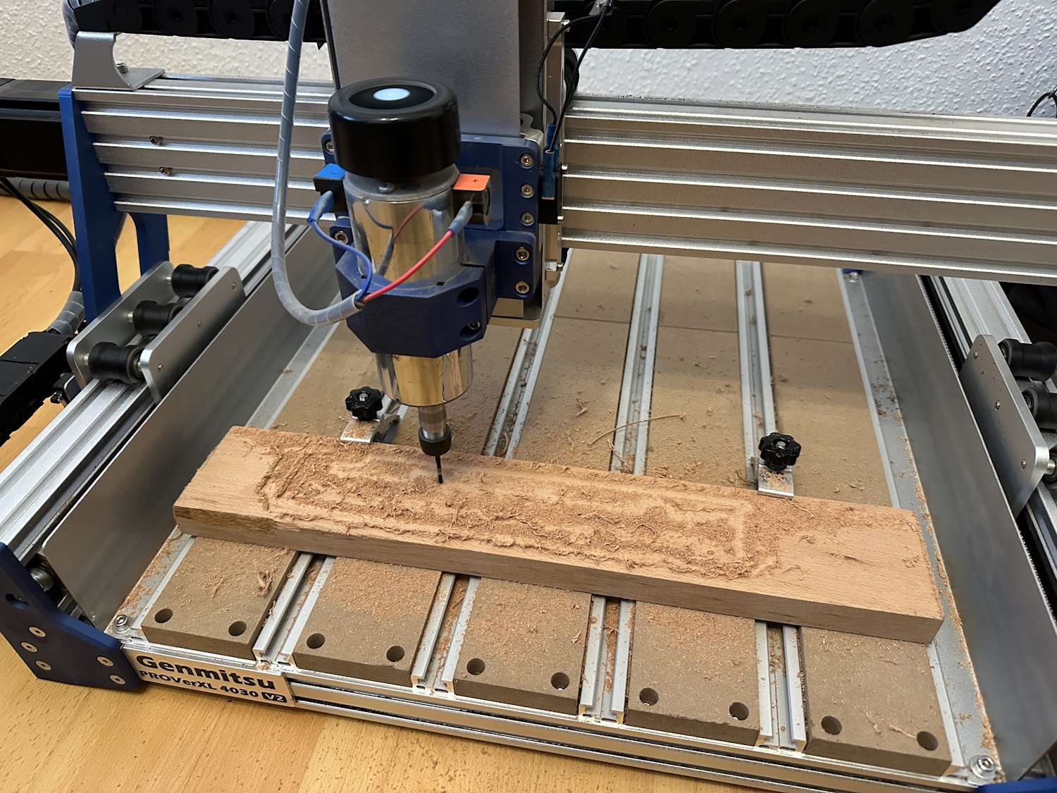
You can compare all Vectric tools and download trial versions on their official comparison page to find the best fit for your needs. For this article, we’ll explore Aspire and create some designs using our Genmitsu 4030 PROVer XL V2. Aspire’s high price is justified for professional use, while VCarve offers a great balance for hobbyists.

All updates for your version are included forever, including new major releases within the first 12 months. The current version is 12, and purchases now will include all 12.x versions and any future 13.x releases until June 2025. There are no monthly fees like Easel or Carveco Maker.

Upgrade options between Cut2D, VCarve, and Aspire allow you to pay only the difference. Additional downloadable cliparts, 2D/3D models, and textures are available to assist in your projects.

Installation

After purchase, download the approximately 500 MB software package from the V&Co portal and follow the setup instructions:

VCarve Postprocessors

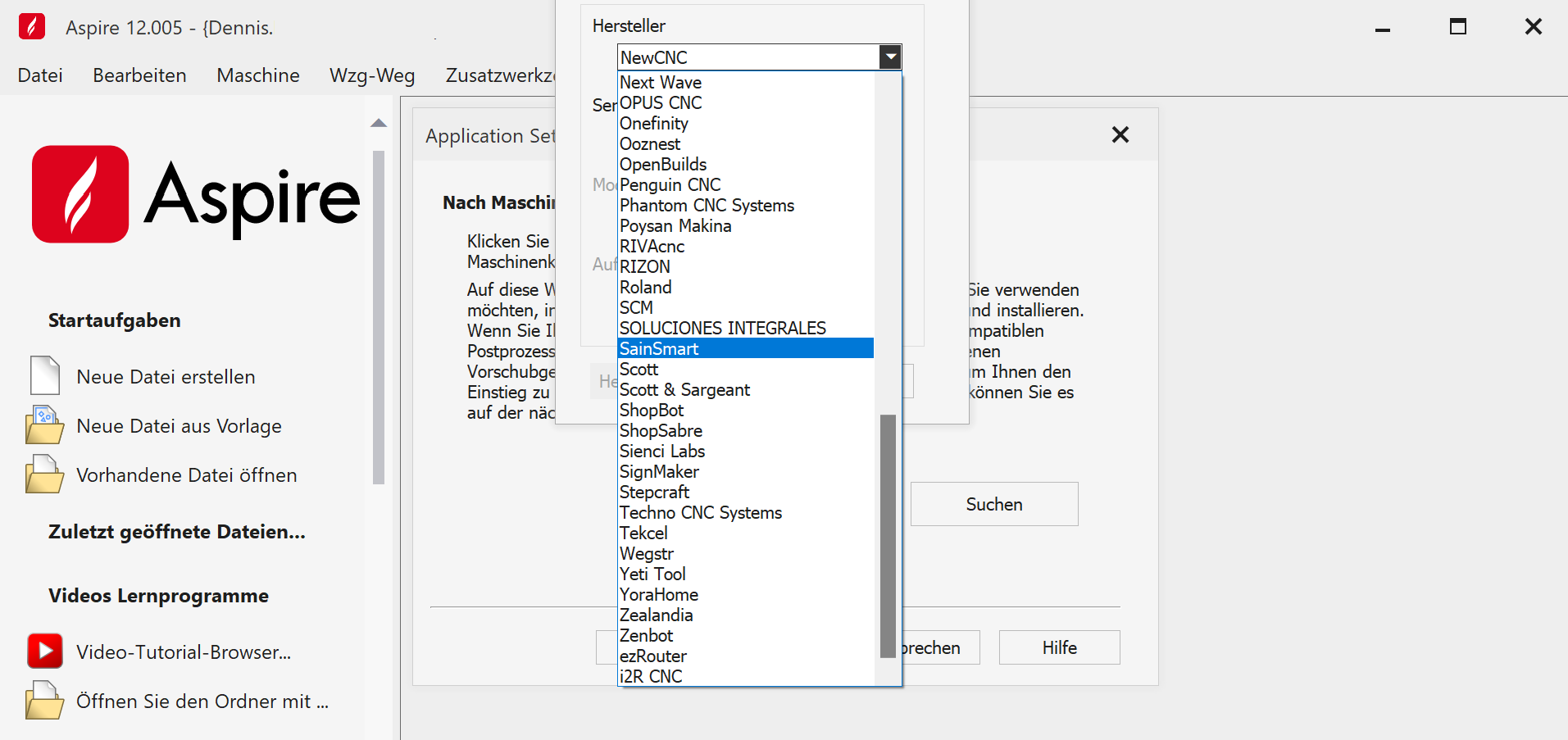
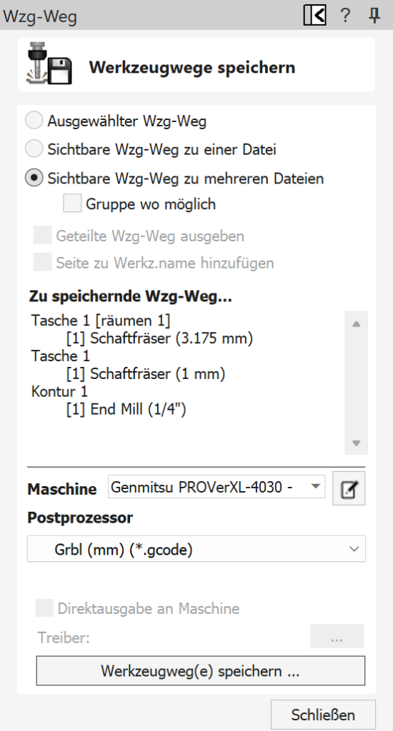
Once installed, the software links to your account and allows you to select your CNC machine, such as the pre-configured SainSmart Genmitsu 4030 PROVer XL V2. Ensure you choose the mm postprocessor for European machines.

Getting Started: Creating a Project

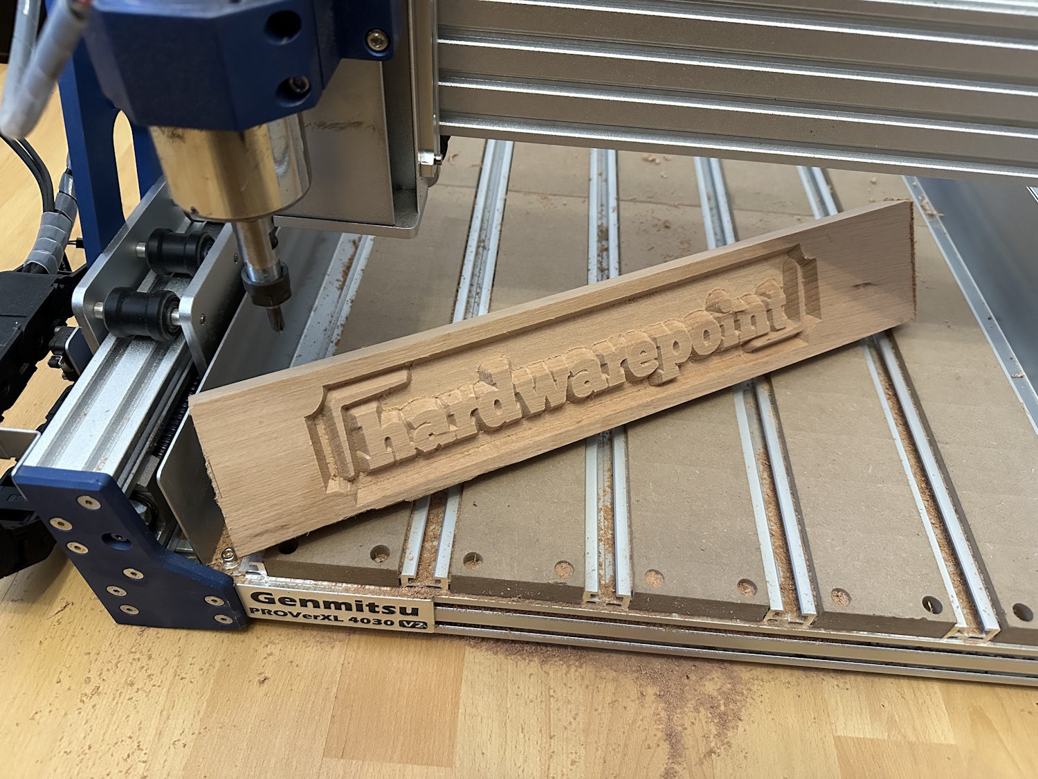
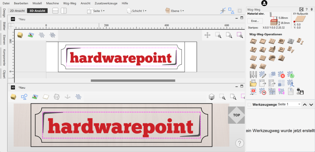
For beginners, we created a simple HardwarePoint sign. Instead of engraving the letters, we raised them using a V-bit to see the resulting effect.

Project Screenshot

The main menu provides links to tutorials with detailed (English) videos that guide you through all features step-by-step, making it easy to follow along.

Material Settings

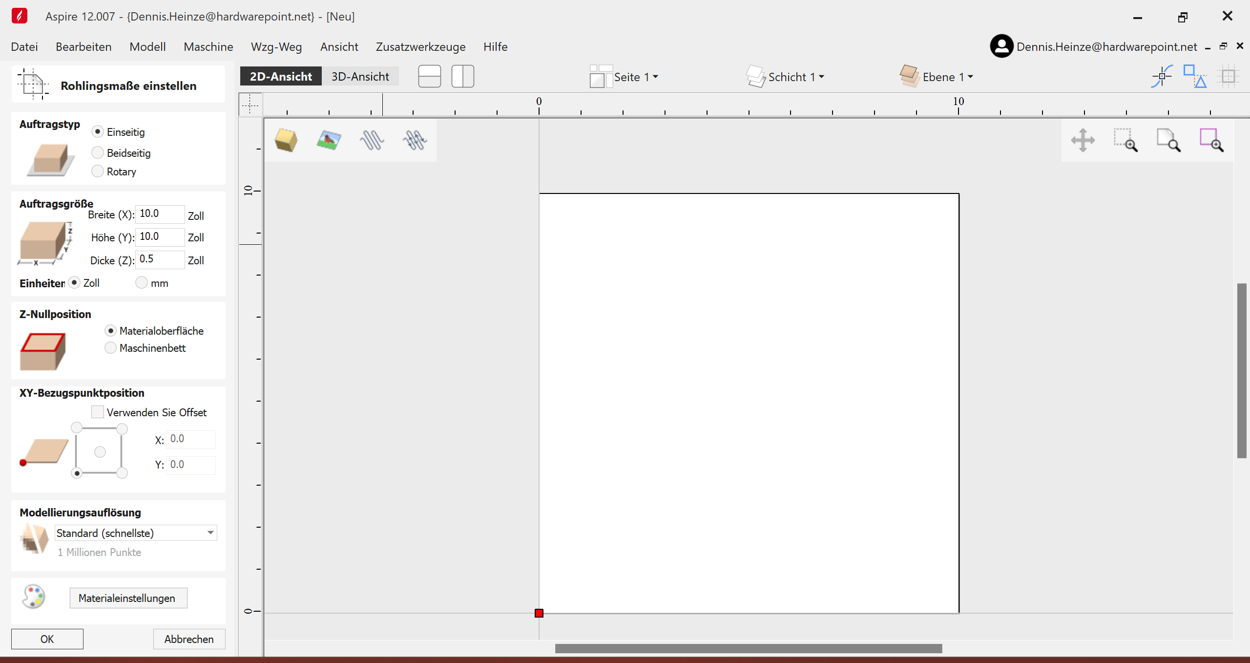
Start by creating a new file, specifying material size and units (mm). Adjust the Z-zero position based on your setup. Most settings default to the workpiece, but you can adjust if using multiple bits.

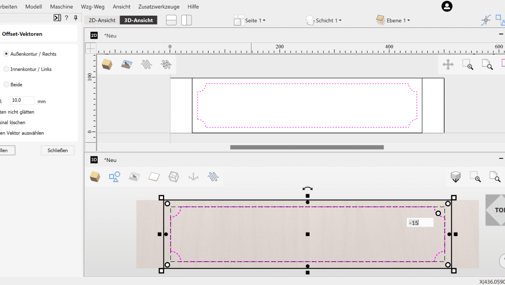
In the 2D view, draw shapes by clicking and dragging. Use the menu for precise measurements. Switch to the 3D view for detailed adjustments and accurate dimensions.

3D View

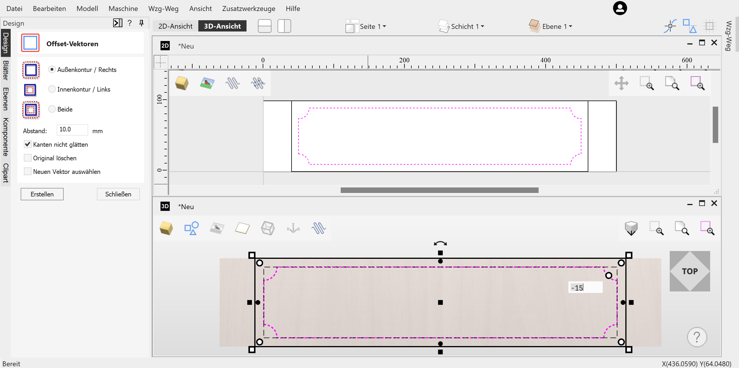
Align and offset vectors as needed. Convert bitmap images to vectors using the “Trace Bitmap” feature for toolpath creation.

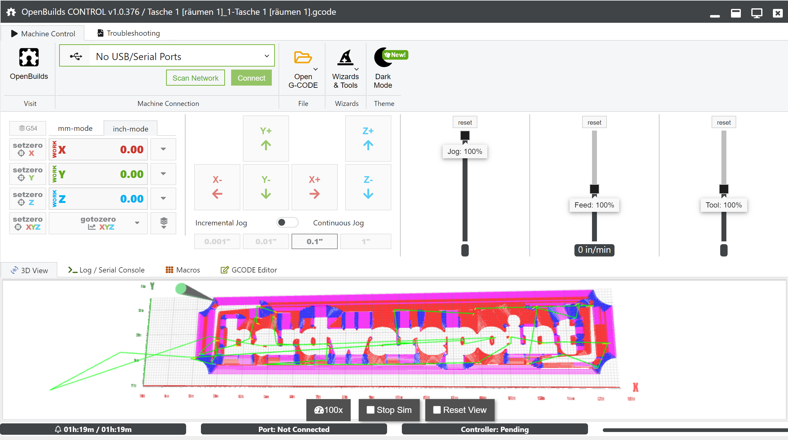
Once satisfied with the design, generate toolpaths by clicking the arrow icon. Aspire translates your design into machine-readable language, ready for CNC machining.

Vectric Aspire’s comprehensive features make it suitable for both hobbyists and professionals aiming to create intricate CNC projects.

For more details and visuals, visit the full article on HardwarePoint.

Toolpaths

To ensure that the design we just created— which, by the way, didn’t take 5 minutes to make—can be executed by the milling machine, appropriate toolpaths must be generated. This is the CAM (Computer Aided Manufacturing) part of the entire process, following the CAD (Computer Aided Design) phase.

Vectric Aspire offers the following toolpath operations:

  • Contour Paths
  • Pocket Tool
  • Drilling
  • Thread Milling
  • Quick Engrave (for Drag-Bits)
  • Inlays
  • V-Groove Milling, Graver Pen, or V-Carve
  • Photo V-Carve
  • Carving
  • Prism Milling
  • V-Carve Inlays
  • Rounded Corners
  • Textures
  • Chamfers
  • Shapes
  • 3D Roughing
  • 3D Finishing
sainsmart

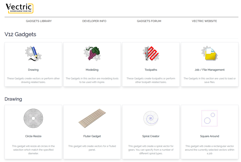
Additional modules can be downloaded as gadgets through “Add-Ons” or even developed by yourself:

sainsmart

Pocketing

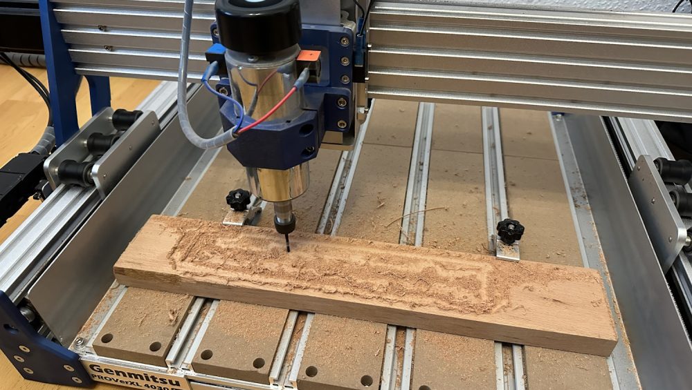
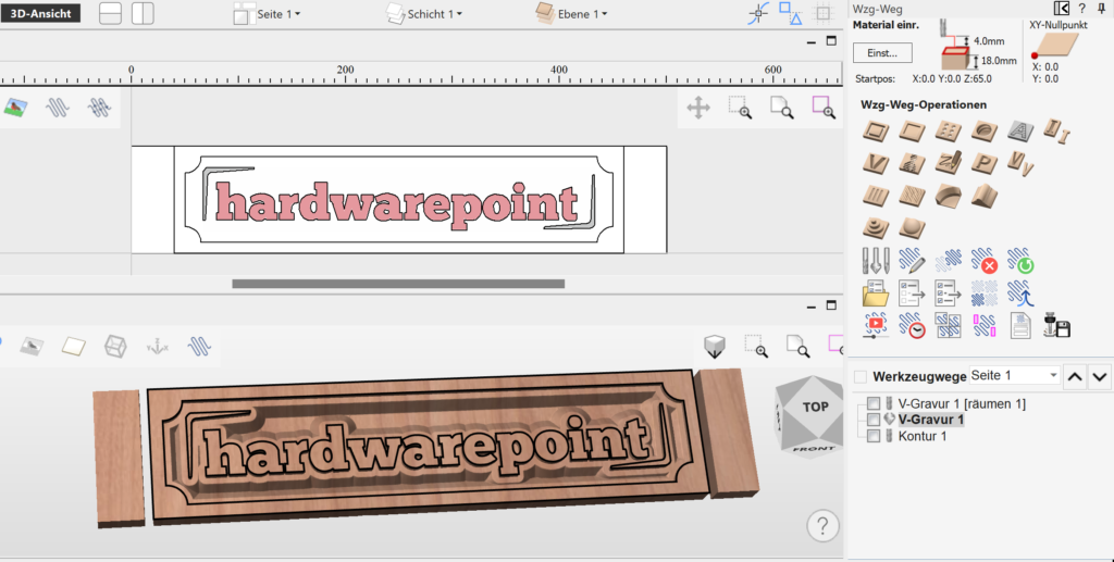
We use the pocket tool to mill the area between the letters and the inner boundary, and then use the contour tool to cut out the component. Later, I chose a V-Carve instead of the pocket to try a different look.

The functions initially seem overwhelming, but you should take a look at each one individually. Aspire automatically selects the appropriate cutters for the function, and all parameters can be explained with images or additional menus. This makes the initial learning curve relatively easy. After experimenting a bit, the corresponding toolpath is simulated and can be previewed. The 3D view not only shows the tool’s path but also how the workpiece will look afterward. This helps in understanding which modes create the desired aesthetics.

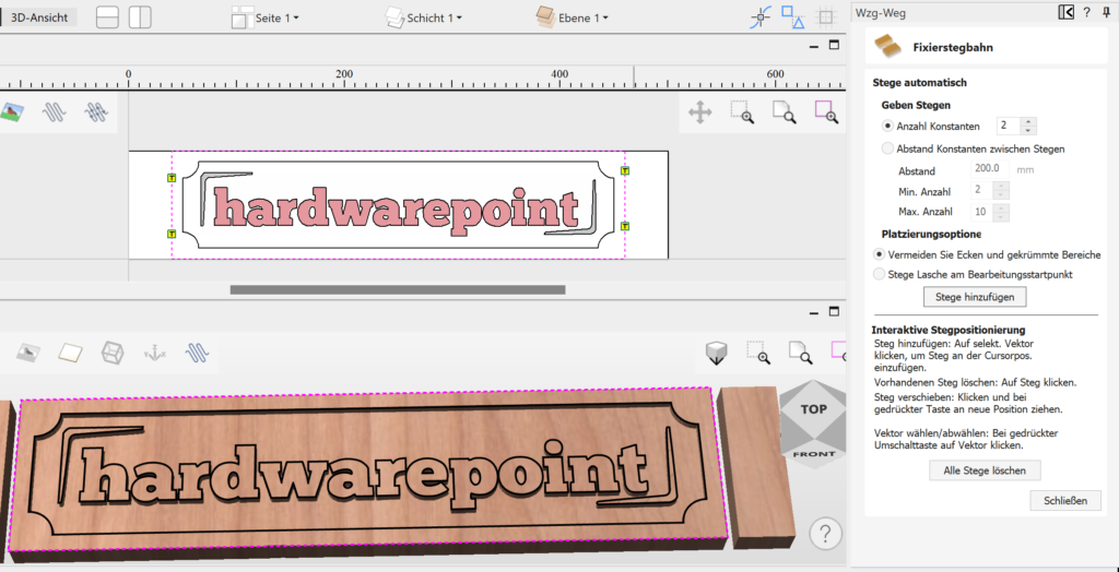
Back to the hwp logo. After drawing a frame over the hwp logo and the inner boundary with the left mouse button in the 3D preview window, these areas are highlighted in pink. Multiple selections in Aspire are done using the Shift key, not CTRL. Clicking on “Create Pocket Toolpath” opens the following menu:

sainsmart

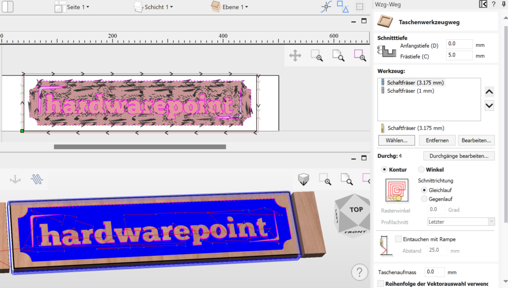
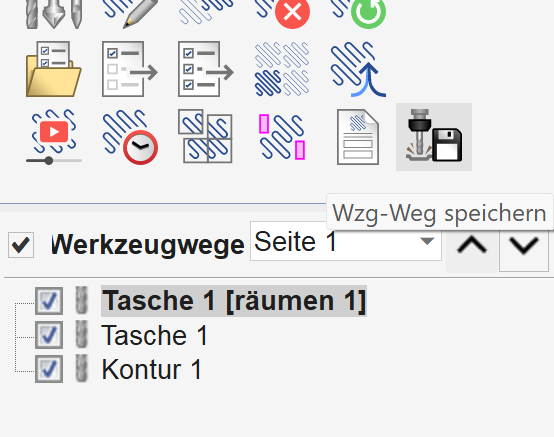
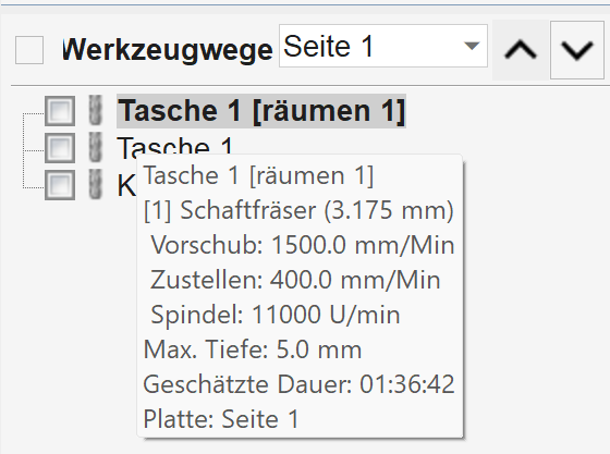
Tool depth C indicates how deep the letters should be milled from the top of the workpiece. Tools can be added via “Select”—for example, a 3.175 mm shank cutter for roughing and a 1 mm cutter for detailing that the larger cutter cannot achieve. Aspire then creates two separate toolpaths, allowing you to execute each tool individually.

sainsmart

Tools

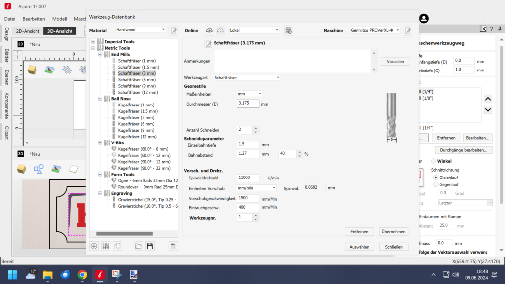
The built-in tool database already includes classifications for both metric and imperial tools as follows:

  • End Mills (Straight End)
  • Ball Mills
  • Ball Nose Mills
  • Conical Mills
  • Graver Pens
  • Corner Radius Mills
  • Profile Mills

These are differentiated for materials such as hardwood, softwood, MDF, and acrylic. Additional databases can, of course, be added, for example from tool manufacturers like SpeTools or Amana, who provide data.

sainsmart

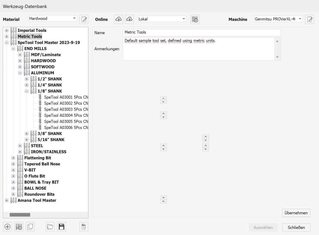
However, you can also create your own tools. Existing tools can be used as a reference, or you can choose to import values from other database entries during creation. This allows you to quickly create new tools and ensures that you are roughly on the right track with the cutting data.

Dimensioned images also show examples and corresponding specifications needed for creating tools, such as spindle speeds, depth per pass, overlap per path, and lead-in/out. After creating or at least selecting a tool, many standard cutters are already available, and by using “Select,” the cutter is added to your job.

“Edit Passes” allows you to view and adjust the cutting depth per pass if you want to deviate from the parameters assigned by the tool/material combination. Metals are available in the material selection but not in the pre-installed tool database.

sainsmart

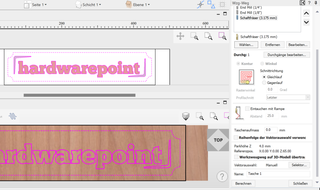
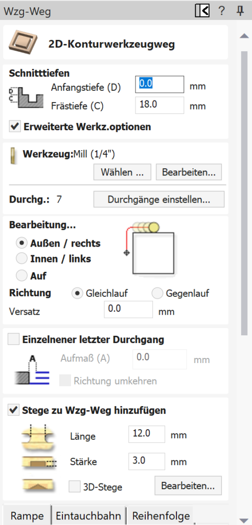
Contour milling allows the cutter to move from the center outward in a circle towards the final shape. For angles, the cutter moves from right to left, depending on the set angle. You can also choose a preceding or subsequent departure from the outer contour. As the menus change based on your selection, it’s easy to understand what each function means, even if the terminology is unfamiliar at first—just experiment. Climb milling (where the cutter rotation and feed direction are aligned) primarily affects the stability of the mill and the finished surface quality. Climb milling demands more from the machine but provides better surface finishes. Generally, prefer climb milling for finishing and conventional milling for roughing.

The “Ramp Entry” checkbox reduces tool wear by angling the cutter between increments in depth, rather than plunging straight down.

The option “Transfer Toolpath to 3D Model” isn’t needed for the example project, but it’s a very helpful feature when 2D paths run over a 3D model, allowing them to adhere to and follow the 3D geometry.

Clicking “Calculate” generates the toolpath.

Categories3DAspire

 Advanced CNC Design with Vectric Aspire

 Simulation

“Preview all tool paths” now shows the process and the final result as a simulation. In this step, preview images can also be created for potential customers, which can be highlighted with colors. By clicking “Close,” we return to the overview of the tool paths and see that two paths have now been created: Pocket 1 Clearing and Pocket 1, Base, as two cutters were previously selected. Clearing or roughing is the coarse work, while Pocket 1 without additional is the finishing work with the 1 mm cutter.

sainsmart

When hovering over Pocket 1 with the mouse, the cutting data appears accordingly; a double-click allows you to adjust the process again.

sainsmart

Contour

Contour 1 already shows the cutout of the sign. The outer vector is marked as a contour, and the contour tool path icon leads you to the following menu:

sainsmart

The menus look very tidy and, in my opinion, are easier to understand than, for example, Carveco Maker. Nevertheless, advanced functions and settings are included. To ensure our component is not completely cut out, we will add a few supports:

sainsmart

If the automated assignment is not effective, meaning the supports are not easy to remove later, they can also be freely positioned. Thus, the first test project is completed, and via “Save tool paths,” these can be exported with the corresponding post-processor for our 4030 PROVer XL.

Export

Three individual files are created, one for each tool used. With vTransfer, the code can also be sent directly to a connected milling machine; however, we use Open Builds Control and now also the wireless module and a tablet for control, more on that in the upcoming article.

sainsmart

Since the appearance with a simple pocket command is nothing special, I tried the V Carve function in combination with a 60° 6 mm V bit cutter. To speed up the process, a roughing pass with the regular 3.175 mm shaft cutter was done first, followed by the cutout using the contour function:

sainsmart

The preview looks interesting, so off to the 4030 PROVer XL; about 1 hour later, the finished part could be held in hand.

sainsmart
sainsmart
sainsmart

These were the first three tool operations, perhaps the simplest and also the most commonly used. Since the hwp logo is a simple 2.5D model, we want to test a real 3D model again before showing you more news in Aspire 12.

2. Project 3D Pike

Aspire comes with an extensive clipart collection. After the remnants from the previous project were still large enough for a 3D milling, I quickly selected something from the pre-installed models. The choice fell on a pike model; the image gallery shows the creation. The model is dragged and dropped from the templates onto our raw material, scaled a bit, and centered. While the 2D view does not really reveal much, the 3D view already shows the finished model. Tool paths are created using 3D roughing and 3D finishing passes. Then it went directly to the 4030 PROVer XL; also after 1 hour, the fish was milled out:

New in Version 12: Alongside the new interface design in Version 12, several new features have been introduced in Aspire, which we would like to briefly examine.

**Image Carving**: With the carving tool, images can be transferred into stylized V-carvings. This appearance can be interesting for some projects and can be created with just a few clicks. In the example, an image of a Datsun: The V-cutter also creates depths and a kind of 3D effect.

**Exclusion Zones**: Vectors can be drawn directly into the design, which will later be avoided by the cutter. For example, the position of the clamps can be defined as an exclusion zone, ensuring that they do not come into contact with the cutter. If the design conflicts with the exclusion zone, a corresponding message is displayed, allowing the user to redefine the exclusion zone.

**2D to 3D Tools**: In the past, Aspire already allowed importing 3D models or using clipart. However, it is now also possible to convert 2D vectors into 3D variants. The stars indicate the different variants, which can be finely tuned using a slider. Three modes can be selected, primarily affecting the top surface of the model: flat, pointed, or rounded. It is also possible to create a custom 3D transformation as a final function. This means not only simple shapes and texts, like in the example, can be transformed into a 3D model, but also complex 3D vectors. When external 3D models come into play, such as STL files from a 3D scanner, the software consumes a lot of hardware resources. At least, that was the initial thought, as the software struggled quite a bit. A look into the settings revealed that a software renderer was selected. Disabling this allowed rendering to occur natively on the graphics card. After a restart, everything ran smoothly. Aspire previously calculated primarily on the CPU, and even with small models, like the sheep as a single component, Aspire could push the CPU usage to 100% with an AMD Ryzen 7800 X3D. The situation can be improved by reducing details via the material tab or during job setup, but the issue is more about software rendering emulation rather than the hardware itself. For pure conversions of vectors and fonts, this is less of a problem. If necessary, one can also work in 2D view and switch to 3D preview only after the design work is completed. However, as mentioned at the beginning, disabling the software renderer should make it run smoothly if you encounter the same problem.

Also new is that adjustments to the project can be made directly in the 3D preview. There is no need to jump back into the 2D area. Since the sheep also has undercuts that cannot be implemented on a standard 3-axis CNC, the model looks a bit funky, but the images are only from a test run. With a two-sided processing, this can be somewhat mitigated, but such a sheep can only be produced with a lot of effort on a 3-axis CNC.

**V-Carving Inserts**: Aspire can generate a suitable insert for a V-carving with just one click. The main project carved in light oak can be completely upgraded with an insert in dark walnut wood. After both components are carved, the insert can be placed in the base and glued. After the drying time, the insert is simply planed, and the two types of wood should seamlessly transition into each other. The tool paths with mirroring and the corresponding distances can be created and generated in just a few minutes. The advantage is faster processing: in our example, 45 minutes compared to 1.5 hours for a V-insert versus a standard insert in the form of individual letters. Additionally, the processing is simpler since the insert is a single piece and allows for very fine work. Curvatures are sharp and not limited by the cutter radius, as the V-bit is also pointed at the bottom.

Conclusion

For every type of CNC processing, a design or CAD program and CAM software is needed to convert the design into understandable code for the cutter based on the available tools. With Aspire, Vectric has a software on the market that is very easy to learn yet offers an immense range of functions. The community around Vectric products, including VCarve, is large, allowing many videos on how-tos and design ideas to be found on relevant platforms. Vectric itself also provides many tutorial videos, making it quite easy for me to get started with Aspire. Previously, I often used the free version of Easel by Inventables, and I will likely purchase VCarve now, as I was convinced by its usability and functionality.

Categories3DAspire

From Zero to CNC: Our Adventure with the Genmitsu 4040-PRO MAX

      Hello,

      My name is Paul Apel. Recently, my son had expressed his desire to become a Machinist. With that being said, I thought it would be a good idea for him to have a way to practice his G-Code at home and be able to work outside of his classes to prepare himself. My interest in helping him sent me down the YouTube path of discovery. I stumbled upon a channel hosted by James Dean. This particular video was a review of the Genmitsu 4040-PRO MAX CNC Machine, 710W Trimmer & Linear Rail Driven, Enhanced XZ Axis with an accompanying giveaway. I told him in the comments that I thought this would be an excellent platform for my son to learn on and submitted my name to his drawing. Lucky ME!!!!, I won.

      After a few weeks, SainSmart shipped me my prize. I must say that the marketing team was very responsive and kind during the process. On that fateful day of arrival, I was very surprised at the overall size and weight of the CNC. I unpacked the shipment and verified that everything was present. In fact, there were a couple of extra screws which I was able to use later. The directions for assembly were very straightforward and easy to follow. When it was completed, my son helped me carry it out to the workbench.

      I now had a beautiful new Genmitsu 4040-PRO MAX sitting on my bench……What to do with it? I told my son he could use it to further his studies. Surprise surprise, a kid who was not really interested in doing something outside class. So I assumed the helm and started trying to figure out what could I do with it. It was just before Christmas, so my wife asked if we could make Gifts. “Of course” I said. I found some trial version CAD software to create our masterpieces.

      Keep in mind, I have never used a CNC machine before, so this was the beginning of an adventure. Looking at the spoilboard, I needed to come to grips with: how was I going to clamp down the stock. The spoilboard is perforated with holes that have threaded inserts for use with the included clamps. I found that given the size and shape of the carving stock, the holes were not always in the right place when using the clamps. Also, I realized that I needed a way to square the material to the machine. I pulled out my framing square and started drawing out the gridlines. This helped, but ultimately it really was not the right answer.

      sainsmart

      I went to the hardware store and purchased hexagonal head bolts to screw into the threaded inserts. This allowed me to square up the material to the machine from an X/Y perspective pretty much anywhere on the board.

      Now that I was able to place my material in a position square to the CNC, I was off…. I began carving and neglected to set up proper dust control. WOW!, I sent wood dust all over the CNC as well as the garage in general. I whipped out the shop vac and began cleaning up the CNC and the nearby area. What I revealed was a very well carved piece of wood! What I also revealed was a lot of wood dust had settled on the rails and lead screws. I cleaned them as best I could, but realized I needed to set up a proper dust collection. I also saw that Sainsmart marketed baffles that mounted along the spoilboard to reduce/eliminate dust settling on the lead screws. I installed a dustboot and baffles. These two upgrades made an amazing difference. I highly suggest these upgrades!

      The next issue I ran into was mounting the material to the spoilboard. I often found myself using the smallest piece of material to carve on. This meant I was running the mill bits over or across the work clamps. The work clamps are relatively small, this combined with the placement of the pre-threaded holes in the spoilboard sometimes limits where to place them and the material. I now use several different ways to hold the material in place based upon the project. 1) blue tape and super glue. (This works well if you don’t care about being precisely aligned because the mill is cutting things out.) 2) the clamps provided along with other scrap pieces to form a friction fit. This allows the clamps to be far from the project and sacrificial wood being near the carving in case you miscalculated where the mill is going to run. 3) Straight up clamping with the provided clamps.

      I purchased the ¼” collet to use my router bits as well as being able to source other CNC bits locally. This allowed for a tremendous amount of flexibility in the bits I can use for carving.

      For my practice carves, I use either foam board, or MDF. Both of these carve up pretty easily and are cheap to use for test purposes. However, I will warn you now, MDF creates a ton more dust than my dust control system can handle. Dust still goes everywhere!

      sainsmart
      sainsmart
      sainsmart
      sainsmart
      sainsmart
      sainsmart

      Overall, I am very happy with the Genmitsu 4040-PRO MAX CNC! This is a nice sized machine with more than adequate power to get the job done. My experience has been nothing short of stellar, with prompt responses and effective resolutions to any issues. Whether you’re a hobbyist or a professional, the Genmitsu 4040-PRO MAX CNC is a worthwhile investment. It’s efficient, reliable, and backed by a company that genuinely cares about its customers. I hope my experience helps make your decision easier—you won’t regret it.

      I am never satisfied, so now I am trying to figure out how to expand my use of this platform beyond wood signs. 3D? Aluminum blocks? I need to find more and more complex projects to tackle with this machine. I think my limiting factor will be my imagination and the CAD software in which I design the projects. Sainmart provides several CAD software trial licenses to experiment with. I highly suggest you try them all before committing to purchase to ensure you get the feature-rich functionality that you need and want.